
搜索历史清除全部记录
- All
- Product Management
- News
- Introduction
- Enterprise outlets
- FAQ
- Enterprise Video
- Enterprise Atlas

Magnetic North
PRODUCTS
U1-Industrial Acoustic Imager (Power Bureau Discharge Version)
Key words:
Ultrasonic acoustic imager
Acoustic imaging
Acoustic leak imager
Domestic acoustic imager brand
Industrial acoustic imaging
Acoustic imaging locator
Acoustic wave imaging instrument
Ultrasonic imaging instrument manufacturer
Introduction to ultrasonic imaging principles
Ultrasonic inspection instrument
Ultrasonic detection instrument
Ultrasonic interface meter
Ultrasonic leak detector
Ultrasonic detector
Ultrasonic analyzer
Ultrasonic detector image
Ultrasonic testing instrument
Ultrasonic monitor
Which brand of imager is best?
Acoustic imager manufacturers
Acoustic imager brand rankings
Top ten acoustic imager brands
Chinese acoustic imager brand
Online acoustic imager
Acoustic and infrared two-in-one imager
Ultrasonic imager quotes
Ultrasonic imaging systems
Visual ultrasonic imagers
Which brand of acoustic imager is best
Visual ultrasonic imager
Ultrasonic imaging detection
Ultrasonic testing equipment price
Industrial ultrasonic imager
Ultrasonic partial discharge location
Acoustic imager for partial discharge location
Ultrasonic partial discharge location imaging
Ultrasonic partial discharge imager
Partial discharge location imaging
Ultrasonic imager
Industrial acoustic imager
Ultrasonic acoustic imaging
Ultrasonic imager manufacturer
Ultrasonic imaging instrument
Intelligent acoustic imager
Ultrasonic imager quote
Ultrasonic imager price
Ultrasonic imager procurement
UAV ultrasonic partial discharge location
intelligent ultrasonic imaging system
Acoustic Imaging Camera
acoustic imager
Partial discharge location
Imager
Acoustic Camera
Ultrasonic Leak Detection Camera
acoustic imaging camera
Ultrasonic imaging equipment
Ultrasonic imaging system
Acoustic imager
akoestische camera
acoustic imager price
acoustic camera
Precision Acoustic Imager
Ultrasonic imaging
Acoustic imaging equipment
Industrial Acoustic Imager
Sound Source Localization
sound imager
sonic industrial imager
industrial acoustic imaging camera
sonic imager
Acoustic imager product images
Acoustic imager images
Smart acoustic imager images
Acoustic imager prices
Ultrasonic imager prices
Smart acoustic imager prices
Smart acoustic imager solutions
Domestic Acoustic Imager Brands
Acoustic Leakage Imagers
Ultrasonic Acoustic Imagers
Industrial Acoustic Imagers
Industrial Acoustic Wave Imagers
Ultrasonic Imager Purchase
Ultrasonic Imager Manufacturers
Visual Portable Ultrasonic Imaging
Visual Ultrasonic Imager
Ultrasonic Wave Imager Repair
Classification:
Share:


Product Characteristics
-

-
MEMS Microphone
132 digital MEMS microphones; frequency range 1K~100kHz
-
-

-
Capacitive Touchscreen
8-inch IPS touchscreen with full viewing angle and high brightness, resolution 1280*800
-
-

-
Working Distance
Working distance 0.5 meters to 120 meters
-
-

-
Adjustable Focus
Camera with adjustable zoom, real-time frame rate up to 25fps
-
-

-
Multi-Source
Supports multi-source mode, each source can display real-time amplitude
-
-

-
Monitorable
Supports headphone monitoring function, allowing real-time monitoring of audio signals;
-
-

-
Fast Charging Protocol
Type-C port charging, supports fast charging protocols such as PD, maximum 60W
-
-

-
Other
Auxiliary lighting;
-
Product Parameters
I. Partial Discharge
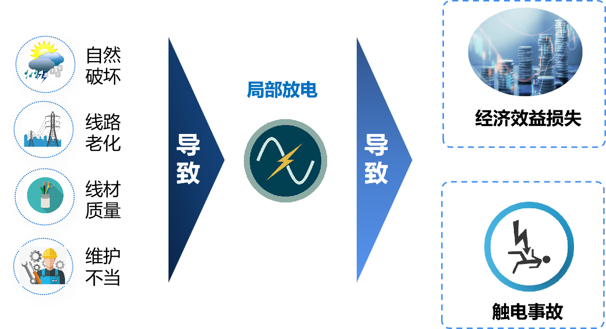
In power systems, insulation defects are common faults. Before an insulation defect occurs, there is a common characteristic: partial discharge. Each partial discharge has some impact on the insulating medium, reducing its insulation strength. If insulation damage occurs, it will cause damage to electrical equipment or even endanger personnel safety. For many years, power companies have been performing partial discharge measurements on high-voltage electrical equipment; partial discharge is a measure of insulation degradation. Accompanied by partial discharge, cracking-like acoustic emission is generated during the process, producing ultrasonic waves that quickly propagate to the surroundings. An intelligent acoustic imager is an intuitive and easy-to-use tool that can identify the acoustic frequency of partial discharge. Using an array of 132 highly sensitive digital microphones, it converts the collected sound into a visible light image, presenting it on the screen in the form of a graph, helping the team to detect and discover partial discharge early.
II. Common Types of Partial Discharge
1. Corona Discharge: This common form of partial discharge occurs when charge is directly dissipated from sharp surfaces of a conductor into the air. (This is the cause of the sound and RF emissions.) Generally, corona discharge is not a concern from a damage or safety perspective.
2. Arc Discharge: Arc discharge is a long-duration discharge caused by gas breakdown. Plasma is generated when current flows through air or any other normally non-conductive medium.
3. Surface Discharge: When a discharge propagates along the surface of an insulator, it is called surface discharge or surface tracking. It can be one of the most destructive types of partial discharge. Contamination and weathering of the insulator surface are two of the most common causes of surface discharge. In medium and high voltage equipment, this discharge occurs when the insulation is damaged (usually due to high humidity or poor maintenance). Moisture ingress is also a common cause of surface discharge.
4. Air Gap (Internal) Discharge: This is usually caused by defects in solid insulation such as cables, bushings, GIS joints, etc. Air gap discharge is extremely destructive to insulation and usually continues to expand until it causes complete failure.
III. Losses Caused by Partial Discharge
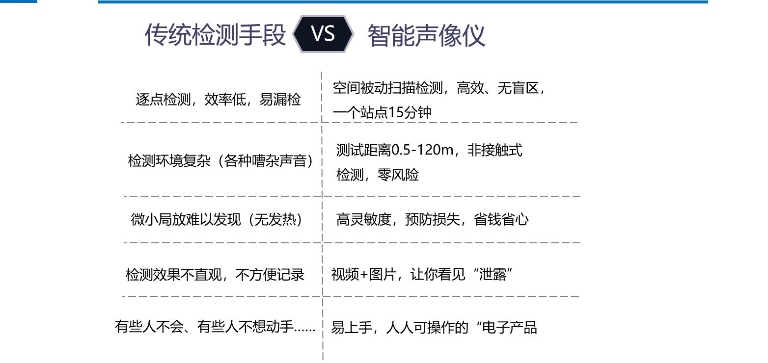
IV. Comparison of Traditional Methods and Intelligent Acoustic Imagers
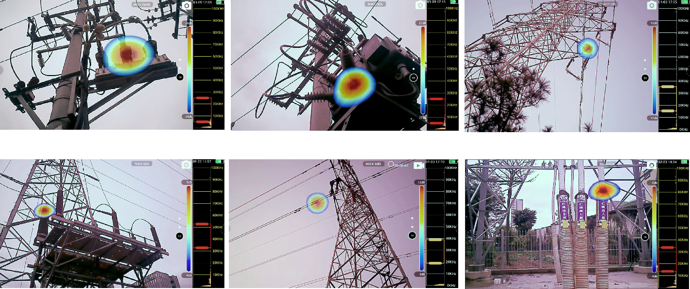
V. Test Site
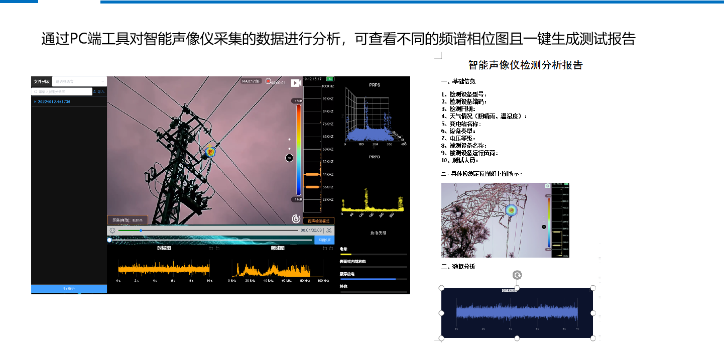
VI. Test Report Analysis
VII. Frequently Asked Questions
1. Can partial discharge of insulators be seen with an infrared thermal imager?
Answer: Possibly. When partial discharge occurs in an insulator, it may cause the temperature of the discharge area to rise. However, this is not always the case. There is also the possibility that the temperature does not change or the change is very small and cannot be detected by a thermal imager. Therefore, it is better to use an acoustic imager to detect partial discharge, and an infrared thermal imager can be used as an auxiliary tool.
2. How far can an acoustic imager measure?
Answer: The detection distance is related to the size of the partial discharge point on site, the voltage level, and the discharge intensity. According to field tests, for common partial discharge faults, the general actual detection distance is generally 0.5-60 meters.
Related products
Hardware products
MDVRS
-

Vehicle-mounted intelligent terminal Z20
The vehicle-mounted intelligent terminal Z20 integrates satellite positioning monitoring, 16 channels 1080P HD video monitoring, 4G wireless communication, emergency alarm, voice broadcasting, LED/LCD display control and rich expansion interface functions. With multi-core processor and powerful neural network engine, it supports a variety of AI intelligent functions, passenger flow statistics, ADAS, DSM, BSD. The vehicle-mounted intelligent terminal integrates scheduling, management, monitoring and passenger flow statistics, and integrates the three key functions of driver behavior analysis (DMS), assisted driving early warning (ADAS) and blind spot detection (BSD). The driver DMS camera can monitor the driver's driving behavior in real time, such as monitoring and alarming the driver's driving behavior such as fatigue driving, smoking, and making phone calls while driving. The front-view ADAS camera can monitor the front dynamics of the vehicle in real time, such as potential collision risks, too close to the vehicle, high-limit road signs and other critical situations, and remind the driver to pay attention through warning tones to effectively avoid accidents. Is a widely used in buses, passenger cars, long-distance trucks and other commercial vehicles in the field of vehicle-mounted intelligent terminal.
-

Bus Intelligent All-in-One Terminal B10-20
The B10-20 intelligent bus terminal integrates satellite positioning and monitoring, automatic stop announcement, bus operation management, 16-channel 1080P HD video surveillance, 4G wireless communication, remote dispatching, emergency alarm, voice broadcasting, LED/LCD display control, and a wide range of expandable interfaces into a single device. Equipped with a multi-core processor and a powerful neural network engine, it supports multiple AI‑based functions, including passenger flow counting, ADAS, DSM, and BSD. The intelligent driving active safety system combines dispatching, management, monitoring, and passenger flow analysis, while integrating three key features: Driver Monitoring System (DMS), Advanced Driver Assistance System (ADAS), and Blind Spot Detection (BSD). The DMS camera at the driver’s seat continuously monitors driving behavior, issuing alerts for fatigue, smoking, or phone use while driving. The forward‑facing ADAS camera实时 tracks conditions ahead—such as potential collision risks, insufficient following distance, or height‑restriction signs—and issues audible warnings to prompt the driver, effectively helping to prevent accidents. This is an in‑vehicle smart terminal widely deployed across commercial vehicles, including buses, passenger coaches, and long‑haul trucks.
-

Vehicle-mounted intelligent terminal Z8
The vehicle-mounted intelligent terminal Z8 integrates satellite positioning monitoring, 8-channel 1080P high-definition video monitoring, 4G wireless communication, remote dispatching, emergency alarm, voice broadcasting, LED/LCD display control and rich expansion interface functions. With multi-core processor and powerful neural network engine, it supports a variety of AI intelligent functions, passenger flow statistics, DMS, ADAS. The intelligent driving active safety defense system integrates scheduling, management, monitoring, and passenger flow statistics, and integrates the two key active safety functions of driver behavior analysis (DMS) and assisted driving early warning (ADAS). The front-view ADAS camera can monitor the front dynamics of the vehicle in real time, such as potential collision risks, too close to the vehicle, high-limit road signs and other critical situations, and remind the driver to pay attention through warning tones to effectively avoid accidents. Is a widely used in buses, passenger cars, long-distance trucks and other commercial vehicles in the field of vehicle-mounted intelligent terminal.
-

New Energy Monitoring Terminal D05
The T-BOX smart terminal D05-20 integrates 3G/4G wireless communication, Wi‑Fi, Ethernet, dual‑mode GPS/BD positioning, and CAN/OBD vehicle data diagnostics into a single device. Designed specifically for modern intelligent connected vehicles, it supports deep reading of vehicle CAN data, enabling the collection, storage, and transmission of vehicle information, as well as analysis of engine emission status and DTC fault codes. It is suitable for both diesel-powered and new‑energy vehicles.
Al Processing Units
-

Binocular passenger flow statistics instrument QC090
The binocular passenger flow statistics instrument QC090 is an embedded product based on non-contact binocular stereo vision technology. The product has the characteristics of powerful function, good scalability, strong stability, and high cost performance. It can be widely used in mobile vehicle environments with strong vibration, such as buses, buses, subways, trains, ships, etc., and can be easily installed in Car doors, roofs, walls, ceilings and other places accurately count the number of passengers passing through.
-

Safe driving assistance terminal QD003
Safe driving assistance terminal QD003 is a vehicle-mounted terminal device in the vehicle comprehensive monitoring information system. AI algorithm is used to process the input data of active safety camera. ADAS can remind the driver before collision or when changing lanes unintentionally. DMS can analyze the driver's fatigue and distraction in real time and issue timely warnings to avoid dangerous accidents. At the same time, the safe driving assistance terminal QD003 can also expand the pedestrian collision function and video monitoring function in the right blind area. The collision warning and monitoring video are sent to the platform server or stored in the SD card of the device through QD003, which is convenient for monitoring and vehicle management.
-

Face recognition alcohol detection terminal QJ001
Face recognition alcohol detection terminal QJ001 is a terminal device integrating credit card attendance, face recognition attendance, body temperature screening, alcohol detection and blood pressure pulse rate measurement. Check the source, it is strictly prohibited for drivers to drive in the state of drinking, and drivers can participate in the operation and production only after passing the test. Carrying out alcohol testing for bus drivers can not only effectively prevent the occurrence of "overnight alcohol", but also instruct and observe the driver's mental outlook and state. It is not only responsible for the driver's personal safety, but also a powerful guarantee for the safety of passengers. In the future, a long-term mechanism will be formed to ensure the safety of passengers while also sounding the alarm for drivers.
Passenger Information System
-

In-car LCD guide screen
28.6 inch bar screen using LED backlight, display brightness more uniform, wider color gamut. Industrial-grade design, with ultra-high reliability and high stability, and the average trouble-free operating time exceeds 50000 hours. Using Hess HI3751V310 two-core multimedia network player-LCD driver integrated board, running Android 4.4. The highest support 4K 30HZ signal input and decoding, decoding ability, system stability. Support bar screen driver display, resolution can be freely switched through U disk, and point-to-point display can be realized. Support stand-alone program playback function, support U disk or TF card playback; The motherboard provides HDMI,TF,USB and other ports to facilitate access to various signal sources.
-

Bus LED display QL010
QL010 series LED road signs are installed on tourist buses, buses and other vehicles, and are used to display LED bus electronic road signs such as line information. Through the vehicle terminal communication, the switching of line information and other contents is realized, which brings convenience to passengers and improves the operation efficiency of bus companies.
-

22 inch TV all-in-one QL022-AH
QL022-AH 22-inch TV all-in-one machine uses a new generation of upgraded IOT intelligent motherboard, which uses RK3568 Cortex-A55 quad-core CPU,2.0G main frequency and Android13 system. Rich peripheral interface, covering USB2.0, USB3.0, RS485, GPIO, network port, high-definition HDMI input and output.
-

Monochrome LED
QL010 series LED road signs are installed on tourist buses, buses and other vehicles, and are used to display LED bus electronic road signs such as line information. Through IPXPT protocol network or vehicle terminal communication, the switching of line information and other content is realized, which brings convenience to passengers and improves the operational efficiency of bus companies.
-

LED sign QL010
QL010 series LED road signs are installed on tourist buses, buses and other vehicles, and are used to display LED bus electronic road signs such as line information. Through IPXPT protocol network or vehicle terminal communication, the switching of line information and other content is realized, which brings convenience to passengers and improves the operational efficiency of bus companies.
Displays
-

7-inch Driver Display Terminal P6
The 7-inch driver display terminal P6 is an interpersonal interaction platform between the driver and the vehicle-mounted intelligent terminal. It has functions such as displaying the working status of the vehicle-mounted intelligent terminal, viewing central messages, checking local recordings and videos, and driver card swiping. It can also automatically adjust the screen brightness according to changes in ambient light and can be expanded with a breathalyzer accessory for pre-shift alcohol testing of drivers. The P6 is feature-rich and easy to operate, making it a widely used vehicle-mounted intelligent terminal accessory in the fields of buses, passenger vehicles, and long-distance trucks.
-

Driver display terminal P7
The driver display terminal P7 is a human-computer interaction platform between the driver and the ITS system. It has the functions of displaying the working status of ITS system, navigation, viewing center messages, viewing local videos and videos, reversing monitoring, etc. And can automatically adjust the brightness of the screen according to the change of ambient light, install customer applications, etc. P7 features rich, easy to operate, is a widely used in buses, passenger cars, long-distance trucks and other commercial vehicles in the field of vehicle display terminal.
-

Driver display terminal P10
The driver display terminal P10 is a human-computer interaction platform between the driver and the ITS system. It has the functions of displaying the working status of ITS system, navigation, viewing center messages, viewing local videos and videos, reversing monitoring, etc. And can automatically adjust the brightness of the screen according to the change of ambient light, install customer applications, etc. P10 features rich, easy to operate, is a widely used in buses, passenger cars, long-distance trucks and other commercial vehicles in the field of vehicle display terminal.
-

Driver display terminal P20
The driver display terminal P20 is a human-computer interaction platform between the driver and the ITS system. It has the functions of displaying the working status of ITS system, navigation, viewing center messages, viewing local videos and videos, reversing monitoring, etc. And can automatically adjust the brightness of the screen according to the change of ambient light, install customer applications, etc. P20 features rich, easy to operate, is a widely used in buses, passenger cars, long-distance trucks and other commercial vehicles in the field of vehicle display terminal.
-

7 inch inverted monitor screen QP001
QP001 is a 7-inch standard definition LCD screen, supports multi-channel video input, supports reversing switch door video switching, and ensures travel safety.
Acoustic lmager
-

Airborne Acoustic Imager U3
The Airborne Acoustic Imager is an acoustic detection device integrating sound source localization and ultrasonic imaging technologies. The device is configured with a DJI-dedicated X-PORT gimbal integrated with the acoustic imager, compatible with DJI M300 and M350 drones. Based on a dual-noise reduction system of drone rotor simulation-based noise reduction algorithms and noise reduction structural design, it boasts excellent anti-interference and stability, easily handling drone noise interference and enabling the detection of minute signals. It can quickly scan and accurately locate partial discharge/gas leaks in high-noise drone environments, displaying the dynamic sound source localization image on the drone remote control screen. Enabling high-altitude flight inspections, it is suitable for remote live-line inspections and fault location of transmission and distribution overhead lines and outdoor substation equipment, proactive preventive maintenance inspections of railway lines and other power equipment, and applications in petrochemicals, forest fire prevention, emergency rescue, industry, and inspection services.
-

Acoustic imager U2
The Acoustic Imager (hereinafter referred to as U2) is a handheld industrial acoustic imager that supports ultrasonic frequency bands. The instrument uses microphone array beamforming technology to acquire sound source distribution data, and is equipped with a high-definition camera to collect video images in real time. By integrating the sound source distribution data with the video images, the changing sound source is dynamically displayed on the screen. The U2 acoustic imager can help you quickly detect possible leaks in air, gas, and vacuum in noisy industrial environments; and it can store the detected images and videos for playback or report generation through image or video capture functions. U2 is also compatible with infrared thermal imaging functions, which can simultaneously capture sound and temperature anomalies, enabling multi-dimensional detection and precise fault location, significantly improving detection efficiency and diagnostic depth. In the fields of electricity, industry, and construction, it can quickly detect and identify partial discharge sound sources and thermal effects, gas leak sound sources and thermal changes, mechanical wear and other problems, providing visual analysis of sound field maps and thermal maps, without the need to switch equipment, improving detection efficiency and accuracy and reducing maintenance costs.
-
")
U1-Industrial Acoustic Imager (Gas Leak Version)
The U1 Industrial Acoustic Imager is a handheld industrial acoustic imager that supports ultrasonic frequencies. The instrument uses microphone array beamforming technology to acquire sound source distribution data, and is equipped with a high-definition camera to collect video images in real time. By integrating the sound source distribution data with the video images, the changing sound source is dynamically displayed on the screen. The U1 Industrial Acoustic Imager can help you quickly detect possible leaks in air, gas, and vacuum in noisy industrial environments; and it can store the detected images and videos for playback or report generation through image or video capture functions.
-
")
U1-Industrial Acoustic Imager (Power Bureau Discharge Version)
The U1 Industrial Acoustic Imager is a handheld industrial acoustic imager that supports ultrasonic frequencies. The instrument uses microphone array beamforming technology to acquire sound source distribution data, and is equipped with a high-definition camera to collect video images in real time. By integrating the sound source distribution data with the video images, the changing sound source is dynamically displayed on the screen. The U1 Industrial Acoustic Imager can help you quickly detect possible leaks in air, gas, and vacuum in noisy industrial environments; and it can store the detected images and videos for playback or report generation through image or video capture functions.
Smart Payment
-

In-vehicle Payment Terminal M10L
The M10L in-vehicle payment terminal is specifically designed for automated fare collection (AFC) systems in public transportation. It supports contactless smart cards compliant with ISO 14443 Type A, Type B, and MIFARE standards, completing transactions in as little as 0.3 seconds. Equipped with an integrated smart card reader, a graphical LCD display, audio capabilities, LED indicators, and a robust waterproof housing, the M10L is ideally suited for a wide range of automated fare‑collection applications.
-
In-vehicle Payment Terminal M10A
The M10A in-vehicle payment terminal is specifically designed for automated fare collection (AFC) systems in public transportation. It supports contactless smart cards compliant with ISO 14443 Type A, Type B, and MIFARE standards, completing transactions in as little as 0.3 seconds. Equipped with an integrated smart card reader, a graphical LCD display, audio capabilities, LED indicators, and a robust waterproof housing, the M10A is ideally suited for a wide range of automated fare‑collection applications.
-

In-vehicle Payment Terminal M10P
The M10P in-vehicle payment terminal is a cutting-edge, intelligent POS device designed to meet current market demands, integrating multiple payment methods into a single solution. Powered by an ARM Cortex‑A53 quad‑core CPU, it features a 4G all‑network‑compatible core platform and runs on Android 13. With robust performance, it supports all 4G, 3G, and 2G networks from the three major carriers, while also enabling Wi‑Fi, Bluetooth, GPS, GLONASS, and BeiDou positioning systems. Offering unparalleled system responsiveness and communication compatibility, this versatile terminal seamlessly handles contactless card reading, QR code scanning, mobile NFC payments, and more.
-

QM095 Cloud Speaker
The QM095 cloud speaker is a small audio device that integrates payment functionality, primarily used by merchants for voice announcements during transactions to ensure that every payment is confirmed and recorded in a timely manner. It comes with built-in network capabilities, allowing it to reliably receive payment notifications even in areas with poor signal. The operation is simple; just plug it in to use, making it suitable for small convenience stores and street vendors. Each successful payment will trigger a clear voice prompt, facilitating confirmation of payment status for both merchants and customers. A customizable TFT color screen version is available, supporting dynamic QR codes and advertisement playback.
-

QM096 Cloud Speaker
The QM096 cloud speaker is a small audio device that integrates payment functionality. The speaker and the code card are designed to snap together for easy disassembly, making it suitable for various practical scenarios with merchants. It allows for flexible payment collection and has built-in network capabilities, ensuring stable receipt of payment notifications even in areas with poor signal. The operation is simple; just plug it in to use, making it ideal for small convenience stores and street vendors. Each successful payment will trigger a clear voice prompt, helping both merchants and customers confirm the payment status.
-

Scan box
The QR code scanner box is a device specifically designed for QR code payment. It typically connects to the merchant's cash register system via USB or Bluetooth, allowing for quick recognition of the customer's payment QR code and transmitting the payment information to the merchant's backend system for processing. It can easily recognize both 1D and 2D codes, ensuring no omissions. The application scenarios are wide-ranging. After a successful scan, it can provide voice announcements to inform about the payment method and amount, enhancing the user experience. It is suitable for various fields such as supermarket checkouts, self-service terminals, and food retail, particularly excelling in scenarios that require fast and efficient transaction completion.
-

Barcode scanner
The barcode scanner scans barcodes using optical principles, decodes the information contained in the barcodes, and transmits it to a computer or other devices via data cables or wirelessly. Its application scenarios are very broad, including supermarkets, logistics and express delivery, libraries, etc., for scanning product and document barcodes. In addition, with the increasing use of barcodes and QR codes, the application scenarios for barcode scanners are also expanding, such as in payment scanning, product traceability, quality control, asset management, government processing, inventory counting, and express logistics.
-

Cloud Printer
Cloud printers are an enhancement of traditional printers with added "cloud" functionality, allowing users to send print jobs directly from their mobile phones, tablets, or computers, breaking the limitations of wired connections and distance. Users can submit print jobs through a cloud platform, and the printer will print the tasks upon receipt without manual intervention. In the food and retail industry, cloud printers can automatically receive and print orders without manual operation, significantly improving work efficiency.
Other
-

On-board sign controller
Car signboard controller, is used to control the LED dot matrix screen related upgrade, display content, display form, change the line and other functions of the product.
-

USB charger QB009
QB009 is a dual-port car USB charger that supports multi-fast charging protocol. It supports A- port fast charging output and has protection such as overcurrent, overvoltage and output short circuit. It is safe and reliable. It can charge the passenger's mobile phone, PAD and other digital products, enhance the passenger ride experience, and improve the service evaluation of passenger transport companies.
-

Bluetooth power amplifier QM060 single spindle
QM060 series Bluetooth power amplifier is a car power amplifier, is a professional long-distance bus, bus, bus, and ship trains and other mobile carriers designed a high-performance multi-function karaoke entertainment system.
-

Life detection sensor QROO1
The life detection sensor QR001 uses radar technology and can detect micro-motion. It can identify if there are any people or animals stuck in a hidden or semi-hidden space.
-

Dual port USB charger QB005
QB005 series product is a USB on-board fast charger that can be installed on passenger vehicles. It provides passengers with charging interfaces for mobile phones, PAD and other digital products, effectively bringing convenience to passengers and improving the overall service satisfaction of passenger transport companies. QB005 series product type has double TYPE-A port output, double TYPE-C port output and TYPE-A port TYPE-C port output three.
-

Dual port USB charger QB010
QB010 series product is a USB car fast charger that can be installed on passenger vehicles. It provides passengers with charging interfaces for mobile phones, PAD and other digital products, effectively bringing convenience to passengers and improving the overall service satisfaction of passenger transport companies. QB010 series product type has TYPE-A port TYPE-C port output one.
-

Infrared Conch Camera QC001
Product name: infrared conch camera Product model: QC001
-

Infrared horizontal waterproof camera QC002
Product name: infrared horizontal waterproof camera Product model: QC002
-

Infrared Conch IPC Camera QC036
Product name: infrared conch camera Product model: QC036
-

Infrared square waterproof camera QC003
Product name: infrared square waterproof camera Product model: QC003
-

PON switch QS001
PON switch is mainly used for vehicle intelligent terminal IPC camera expansion scene, supporting applications in the field of vehicle monitoring.
-

USB charger QB008
QB008 is a single-port car USB charger that supports multi-fast charging protocol. It supports A- port fast charging output and has protection such as overcurrent, overvoltage and output short circuit. It is safe and reliable. It can charge the passenger's mobile phone, PAD and other digital products, enhance the passenger ride experience, and improve the service evaluation of passenger transport companies.
-

Car Internet Router QM003
Car router QM003 is a high-performance industrial router, its CPU frequency is less than 560MHz, can calmly face a variety of applications. The hardware based on Qualcomm Atheros WiFi technology has super performance and strong anti-interference ability, which enables the on-board router to work stably in various complex environments.
-

Three-roll gate
The three-roller gate is a type of passage control device mainly used to manage the entry and exit of personnel. It consists of three metal rods forming a spatial triangle, usually made of hollow, closed stainless steel pipes, which are sturdy and not easily deformed. It achieves blocking and releasing through rotation; it is suitable for office locks, commercial places, and public areas such as buses, ferries, and bus stations.
Leave Us A Message Now
Attention: We Can Produce Customized Products. If Necessary, Please Make Sure To Accurately Fill In The Information And Maintain Smooth Communication. We Will Contact You As Soon As Possible.
Social Media
Contact Information
Add: 6F-8F, Building #6-2, Anren Industrial Park, Xiamen City, Fujian Province, China
E-mail: market@amoymn.com
After-sales email: services@amoymn.com
All Rights Reserved © 2024 Xiamen Magnetic North Technology Co., Ltd.
